Table of Contents
This page has deprecated and will be archived. Please go to https://www.bitcraze.io/.
Introduction
What is the Crazyfile Nano Quadcopter used for
It can be used for a number of things but the primary usage is as a development platform and for quadcopter enthusiasts that would like a nano-quad. Here's a list of some possible uses:
- Implementing and testing control algorithms
- Adding functionality using the expansion interface
- Creating applications on the host side that control the quadcopter
- Help us out with implementing new features and finding/fixing bugs to make it an even better platform
What do you need for flying
Here's a short list of what is needed for flying:
- A controller for input of flight commands (joystick). Currently Playstation 3 and Xbox 360 controllers are supported out of the box, but any controller with at least 4 analog axis can be configured and used. Se the input-device page for more information.
Basic concepts
 The Crazyflie is controlled from a computer using an input device such as a game controller (PS3 or Xbox 360). A USB radio dongle is used to send control data from the controller/computer to the quadcopter.
Flying
The Crazyflie has 4 different controls: roll, pitch, yaw and thrust. Changing the roll and pitch will make the quadcopter tilt to the sides and thus change the direction that it's moving in. Tilting the quadcopter forward will make it go forward and the same applies for every other direction. Note: the images below show the front as setup in X configuration. Normal (out of the box) configuration has the front inline with motor M1.
![[pitch,roll & foward]](/_media/projects:crazyflie:userguide:crazyflie_directions_pitch_roll.jpg "[pitch,roll & foward]")
![[yaw and "front" orientation changing]](/_media/projects:crazyflie:userguide:crazyflie_directions_thrust_yaw.jpg "[yaw and \"front\" orientation changing]") Changing the yaw will make the quadcopter spin. Changing the yaw is normally not a good idea for beginners since this will also change what direction is forward for the quadcopter.
Changing the yaw will make the quadcopter spin. Changing the yaw is normally not a good idea for beginners since this will also change what direction is forward for the quadcopter.
The thrust is used to control the altitude of the quadcopter.
Radio communication
The frequency used communication is based on 2.4 GHz. For every quadcopter it's possible to set a channel between 0-127 (only 0-80 is allowed worldwide) that will be used for communication. This means that once the channels is set for a quadcopter you will have to specify the appropriate channel when communicating with it. The channel can be set within the service tab of the Crazyflie client pc-program.
Durability
The Crazyflie is contructed without a separate frame, it uses the PCB as a frame and simply attaches four motors to it. This means that the weight of the platform is very low and on most impacts it simply bounces of objects. If you are unlucky either propellers or motors might break when crashing. If so have a look at our troubleshooting page for some basic troubleshooting and repairs. If you are very unlucky due to a severe crash you might break one of the PCB arms. We are working on a 3D printed plastic patch that could fix this. Either way handle the Crazyflie with care as it is not unbreakable
Basic usage
Getting started
- Power it on by pressing the side-mounted push-button
- Hold the Crazyflie stable during the start-up, otherwise the sensor tests may not pass. Each motor will quickly turn on to indicate that they are working.
- Place the Crazyflie on a stable surface (the floor is the best)
- Wait until the red LED shows that the sensors are calibrated by increasing the blink rate from 1Hz to 2Hz.
- Connect to the quadcopter using the computer application
- The green LED will now start flashing indicating that the radio communication is working
- Use the controller to control the movement of the quadcopter
- Fly around :)
- When the red LED is continuously lit or/and the copter becomes uncontrollable the battery is low. Recharge and start over.
For more tips on flying take a look at the tips and tricks page.
The Crazyflie
Below are the basic components mapped out on the Crazyflie.
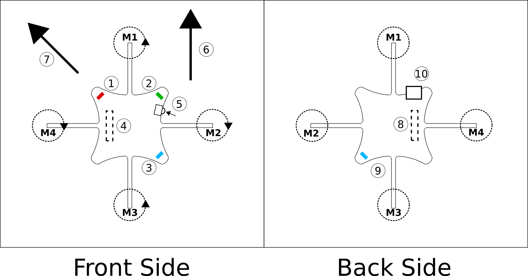
- Red LED - Shows system alive and charge status
- Green LED - Shows radio communication and charging status.
- Blue LED - Shows power on status
- Expansion - Can be used to expand functionality by adding hardware
- Power push-button - Push button to switch the Crazyflie on/off (Note that this is a push button, not a sliding button)
- Front direction when flying in normal configuration
- Front direction when flying in X configuration, blue LED is at the tail.
- Expansion - Can be used to expand functionality by adding hardware
- Blue LED - Shows power on status
- uUSB charging - Used to charge the battery
LED indications
The Crazyflie has four LEDs mounted, two blue, one red and one green. The two blue LEDs indicate that the system is powered and the red/green shows operation.
When the Crazyflie is powered the two blue LEDs will be lit up and the red/gren LED will blink shortly indicating that the bootloader is executing. After this the firmware will start up.
During firmware startup:
- Green LED
- Tests passed: 5 quick flashes
- Red LED
- Tests failed: 5 quick flashes. This can be caused by too much movement of the Crazyflie when powering it on. Try putting it on a stable surface and try again.
When USB is connected:
- Green LED
- Charging: Blinking at 1 Hz with a duty cycle showing the battery charge level. The longer on time the more charged the battery is.
- Fully charged: LED steady lit
- Red LED
- System alive: 1 Hz heart beat
When USB is not connected:
- Green LED
- Radio communication: LED blinks for every packet received. When the LED starts to blink slower this indicates that the radio reception is getting bad
- Red LED
- System alive: 1 Hz heart beat
- Sensors calibrated: 2 Hz heart beat. Crazyflie now ready to fly.
- Charging needed: Red LED steadily lit. “Fly back to base!”
Firmware behaviour
All these behaviours can be compile time configured. In the future they might as well be able configurable during runtime using the Crazyflie client.
- Radio communication lost
- If the Crazyflie hasn't received any commander package within 0.5s it will try to level itself. The client sends out 100 control packets per second so 50 consecutive packages must have been lost
- If the Crazyflie hasn't received any commander package within 2s it will turn off the all motors.
- Inactivity shutdown
- If the Crazyflie hasn't received any commander package within 5min it will automatically shut down.
The USB Radio dongle
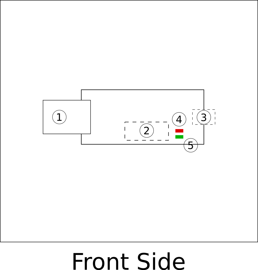
- USB - Connect to computer
- Programming/PPM interface - Used for programming and interfacing with a RC remote
- Antenna connector - Connector for antenna
- Red LED - Toggles when data is now able to be sent to the quadcopter
- Green LED - Toggles when data is successfully send to the quadcopter