
Products
-
-
- Accessories
- Breakout boards
This page has deprecated and will be archived. Please go to https://www.bitcraze.io/.
This page has details about how to assemble the Crazyflie nano quadcopter kit.
Before you go ahead and assemble the Crazyflie check the Crazyflie control board and the Crazyradio electronics:

1. Attach a powered micro-USB cable to the Crazyflie control board. It should power up and blink 5 times with the green LED. After that the green LED should be fully on and the red LED should blink.
2. Attach the Crazyradio to a computer and follow the installation instructions. When the Crazyradio is found and enumerated the red and green led will turn off. This is a good sign.
3. When the cf-client is installed and the Crazyradio is working it should be possible to connect to the Crazyflie using the connect button in cf-client. Test that you can connect. It is also a good time to update the firmware now using the bootloader. Latest stable binaries can be found here.
When all these tests passed go ahead and start the assembly. If they did not pass visit the forum and open a support thread if you can't already find one describing the problem.
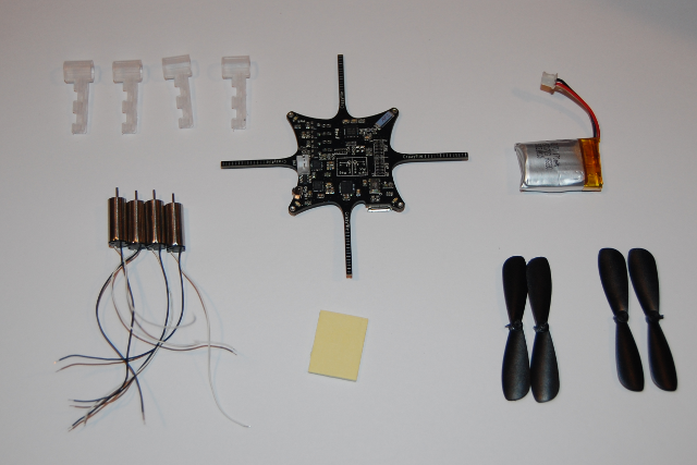
1. Check that you have everything that's needed
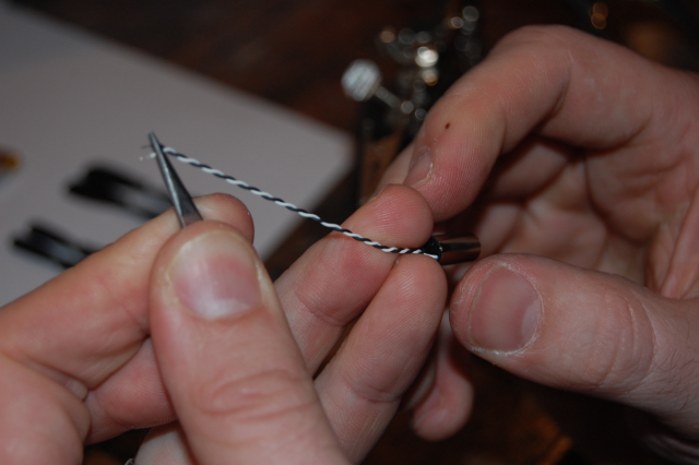
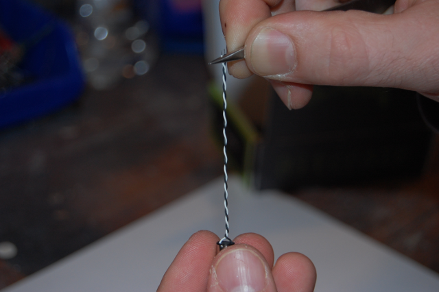
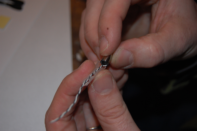
2. Twist the two motor wires together so they are easier to handle (and electromagnetic noise is reduced)
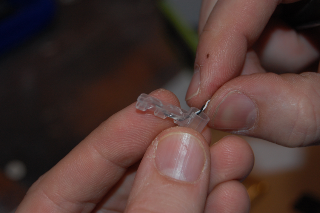
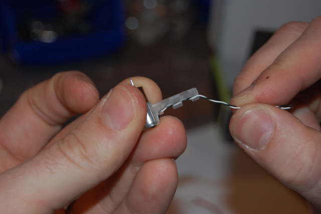
3. Thread the twisted motor wires through the motor mount arm section. It can be a bit tricky so have patience.
4. Insert the motor into the motor mount and be careful to not damage the motor wires while inserting it.
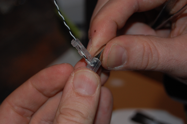
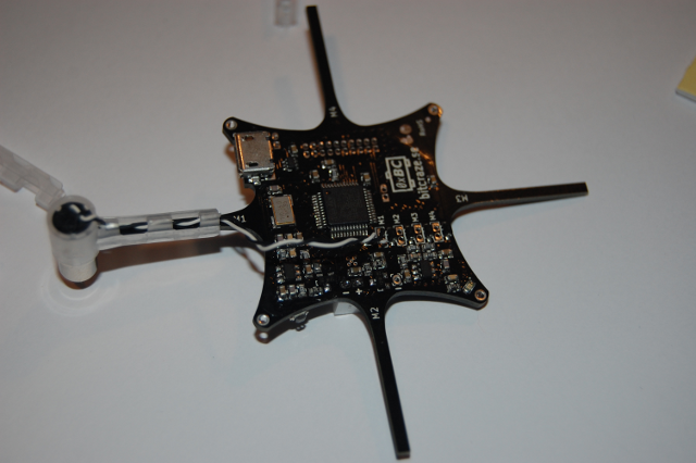
5. Press the motor mount on to the PCB arm. Be careful not to damage the wires when you do it. Start with M1.
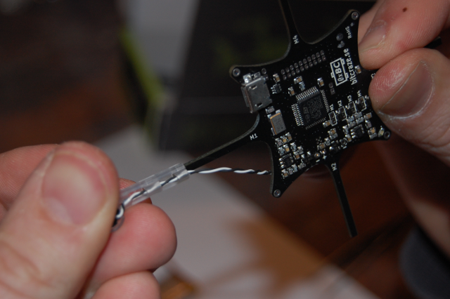
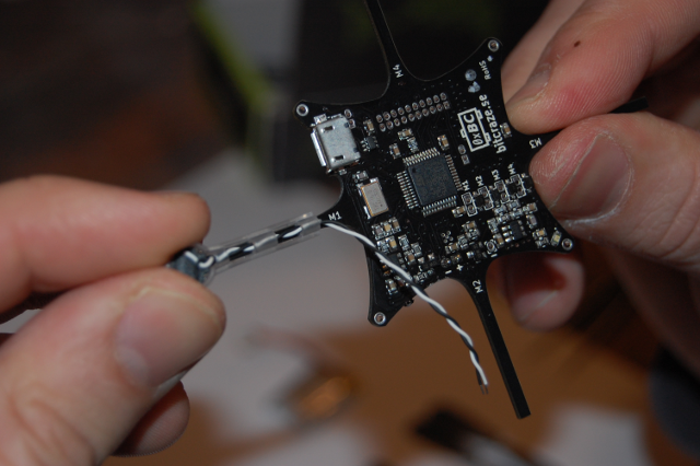
6. Try to attach the peeled end of the motor wire into the motor through hole pad. Start with white wire on round pad on M1.
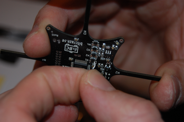
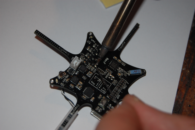
7. Turn the PCB around carefully not removing the wire from the hole and solder it from the top of the PCB. The square pads can take a bit longer to heat up as they are connected to the battery supply copper plane.
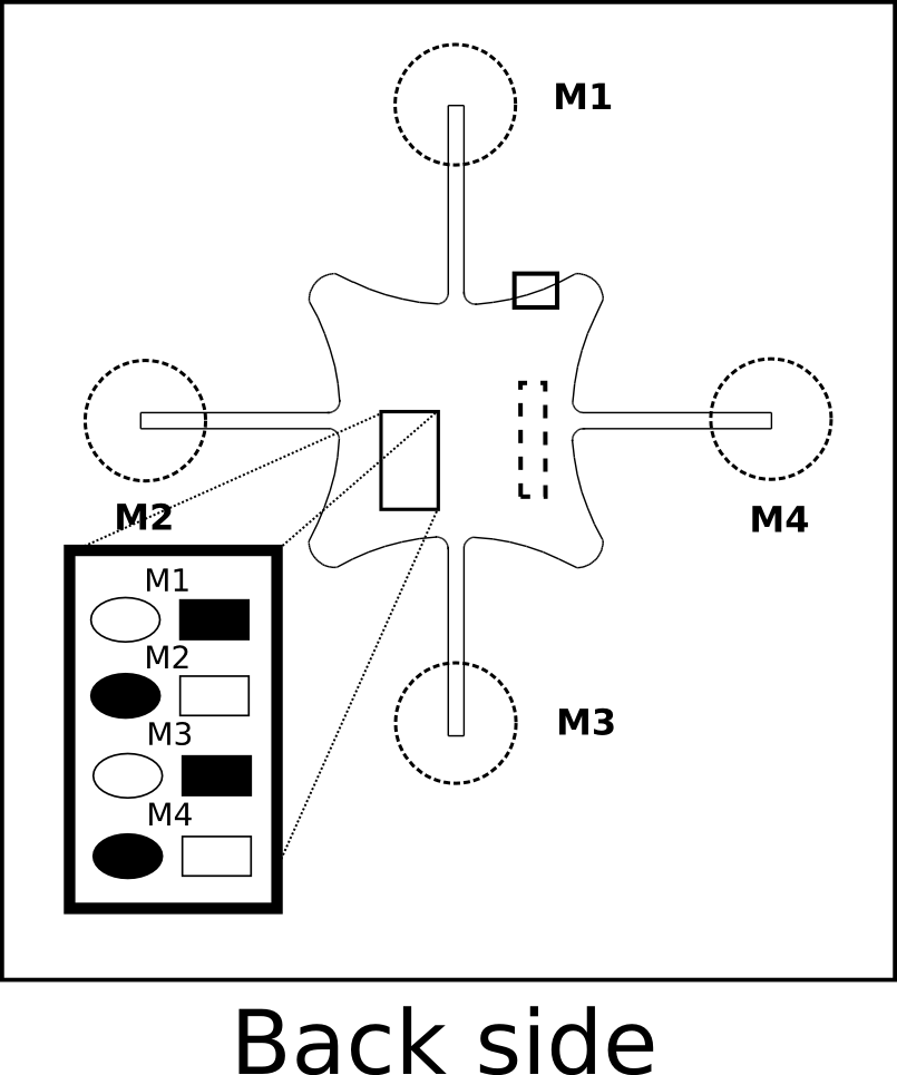
8. Repeat step 2-7 for the rest of the arms M2, M3 and M4 and remember to alternate the white and black wires according to the picture .


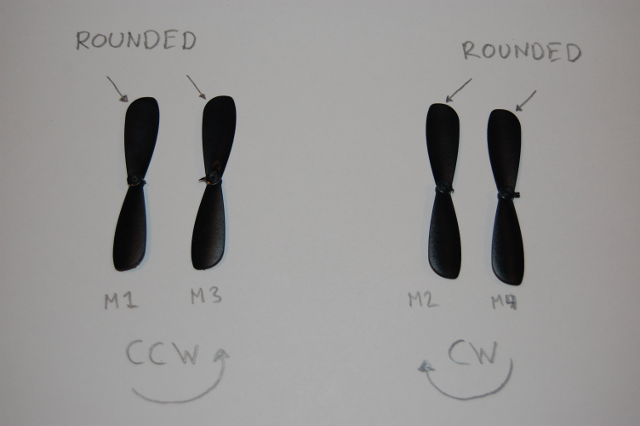
9. Attach the propellers (see drawings below for mapping). ![]() You got two different packs of them with your kit, one with five clockwise and one with five counter-clockwise ones, take care to really use propellers from both packages, not just mounting two of them upside down, your drone won't fly otherwise
You got two different packs of them with your kit, one with five clockwise and one with five counter-clockwise ones, take care to really use propellers from both packages, not just mounting two of them upside down, your drone won't fly otherwise ![]() . Your clockwise propellers may be labeled with an “A”, otherwise look at the curvature of the tips to determine which is CW and which is CCW. The dull surface goes up, the shiny surface goes down. You will also see a small molded ring on the top surface. We recommend you sorting out the best propellers. See maximizing performance
. Your clockwise propellers may be labeled with an “A”, otherwise look at the curvature of the tips to determine which is CW and which is CCW. The dull surface goes up, the shiny surface goes down. You will also see a small molded ring on the top surface. We recommend you sorting out the best propellers. See maximizing performance
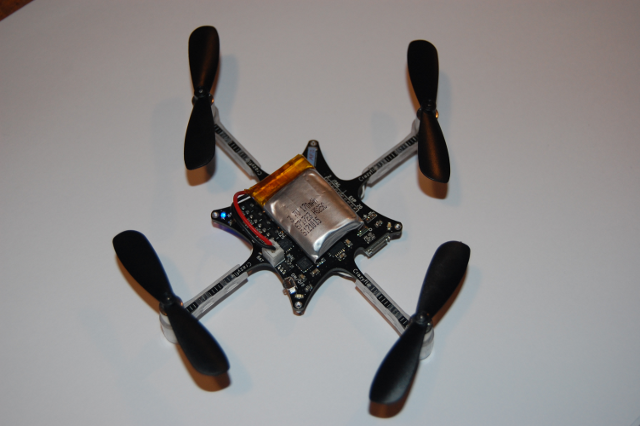
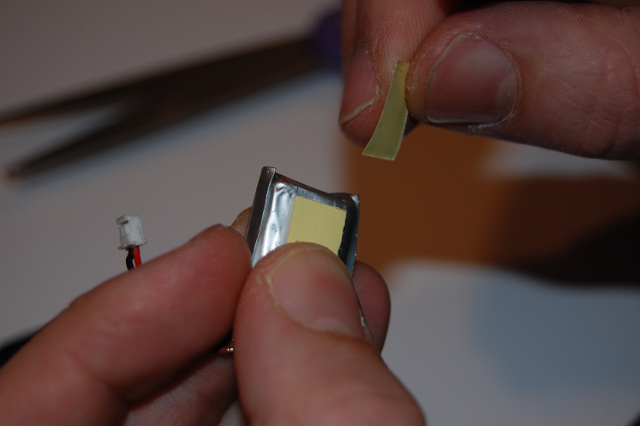
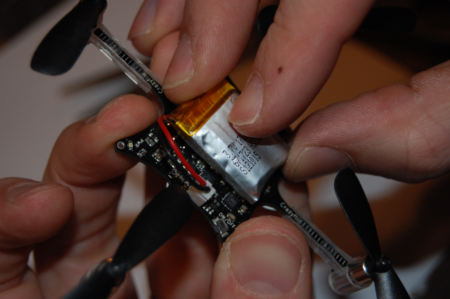
10. Attach the battery and try to centre the weight on the PCB as good as you can.

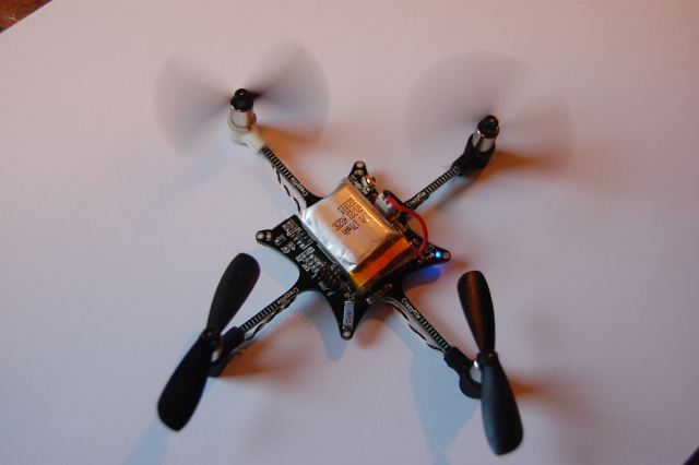
11. Before you power it on visually inspect your soldering for shorts. Make sure any copper from the wires are not sticking out so they could short to either of the two resistors next to M3 or to anything else. You can also use a ohmmeter to check for a resistance of about 2 ohms between each pair of pads. After that power on (carefully push in the button with your fingernail - it is not a slide switch) and check that all motors spin during start-up and in the correct direction.

Assembly video using new motor mounts
The following images show how to solder the motors and attach the propellers. The black pads should have the black wire attached and the white pads should have the white wire attached.

")
